Friday, 27 May 2016

Conning Tower #1

The conning tower has been started!   Now I can start putting together the hatch, windows, diving planes, dash and electronics.  The fun stuff.


Fig. #1.  Assessing the gaps that need to be welded.  The whole tower needs to be lowered by about 20 mm in order to sit flush with the rest of the hull.

Fig. #1
21/05/2016
Fig. #2.  After running around the conning tower with a fine tipped marker I had the basic lines that needed to be cut.  The shallow ribbing in the drums make this quite fiddly.

Fig. #2
21/05/2016
Fig. #3.  Sitting nicely against the hull.  The gaps range from 2 mm to 4 mm .  Not perfect but good enough to weld.

Fig. #3
21/05/2016
Fig. #4.  After getting the tower level and at right angles to the rest of the hull, the first weld goes on. 

Fig. #4
21/05/2016
Fig. #5.  Making sure that the frame for the hutch fits. 

Fig. #5
21/05/2016
Fig. #6.  From the inside I cut into the hull and bent the flaps up to match the tower.  I'm not sure if I'll weld these to it yet or not.  It might turn out to be too fiddly in the small space.

Fig. #6
26/05/2016
Fig. #7.  All bent upward.  There's actually a lot of room once your in. 

Fig. #7
26/05/2016
Fig. #8.   Cleaning off the paint ready to weld it. 

Fig. #8
26/05/2016
Fig. #9.  The start of a long welding process.  All the welds on the 1 mm steel have been down at around 50 - 60 Amp, depending on how fast I move.

Fig. #9
26/05/2016
Fig. #10 to #12.  The outside welds. 

Fig. #10
26/05/2016

Fig. #11
26/05/2016

Fig. #12
26/05/2016

Not sure what'll be next, but I'm thinking I'll start putting some ribbing inside for extra strength.

Tuesday, 24 May 2016

Ballast Release System #2

Here's an update on the ballast release system.  I've welded together the brackets that will hold the gears in place for unwinding the bolt that will hold the concrete block to the sub.  The gear ratio is 9:1, so nine turns of the handle will give me one turn of the bolt.  It should take about three or four turns of the bolt in order for the concrete block to drop.


Fig. #1.  Cutting the side bracket to length and prepping to weld.

Fig. #1
14/03/2016

Fig. #2.  The side bracket welded.

Fig. #2
14/03/2016
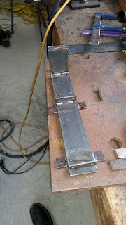
Fig. #3.  Cutting out the curve so that it fits around the main shaft.

Fig. #3
19/03/2016
Fig. #4.  The front bracket welded together.  This part will house all the bearings required for the reducing gears and their shafts.

Fig. #4
19/03/2016
Fig. #5.  A quick mock up of everything together to make sure it all fits.  Looking good.

Fig. #5
19/03/2016
Fig. #6.  I had to weld a couple of braces to the seat brackets so that I could cut out the center of them to fit everything in.

Fig. #6
22/03/2016
Fig. #7.  This is where the system will sit, between the seat brackets and rudder cable wheels.

Fig. #7
21/03/2016
Fig. #8.  One if the end bearing holders.

Fig. #8
21/03/2016
Fig. #9.  The main bracket ready to go.

Fig. #9
22/03/2016
Fig. #10.  Making sure that the water pipes fit in with the mechanism.  It's a snug fit but it works.

Fig. #10
22/03/2016
Fig. #11.  The back bracket ready to weld in.

Fig. #11
22/03/2016
Fig. #12.  Back bracket welded in place.

Fig. #12
22/03/2016
Fig. #13.  I welded the front brackets onto the hull and now the whole system needs fine tuning.  Some of the gears need holes drilled in there sides for grubs screws, and the top plate needs to be made to hold everything steady.  Then the shaft that will hold the concrete to the submarine needs to be threaded.  I'll be doing that after I have finished the hull so I can begin pressure testing and leak testing.

Fig. #13
21/05/2016
The next update should be on welding the conning tower together.