Saturday, 31 December 2016

Pressure Test #1

Fig. #1.  On Thursday I started preparing for pressure testing.  I used Sikaflex to seal up the light covers and the plate that will soon hold the diving planes to the hull.

Fig. #1
29/12/2016

Fig. #2.  The back window sealed in place.  It's made from 3mm thick poly-carbonate.

Fig. #2
29/12/2016

Fig. #3.  Breaking out the vacuum pump I bought off Ebay over a year ago.

Fig. #3
29/12/2016

Fig. #4.  The front window sealed on.  Like the rear window this is also made from 3mm thick poly-carbonate.

Fig. #4
29/12/2016

Fig. #5.  I'm using the air inlet for the main ballast tanks as the point to where the vacuum pump will hook up to.  I've also added a vacuum gauge to it as well.

Fig. #5
29/12/2016

Fig.  #6.  Sealing up the rear.

Fig. #6
29/12/2016

Fig. #7.  I'm still not sure how I'm going to do the seal for the hatch, but here I started using Sikaflex and baking paper on the lid itself in the hopes that once the Sikaflex dried, the baking paper could be peeled off and it would leave a nice soft seal for the hatch to be clamped onto.  However I didn't have time to wait (there was also a bit of impatience involved) so I just sealed the whole dome down and will later remove the seal with a wire disc in the drill.

Fig. #7
30/12/2016

Fig. #8.  The first pressure test currently at about one meter down.  It's nearly -10 kpa (-0.1 on the gauge) which is about -1.4504 psi.

Fig. #8
30/12/2016

Fig. #9.  Here I'm at two meters down (approx -2.9 psi) and then I found some small holes in a few welds (Fig. #11 to #13).  Once I stopped the pump I could here the air rushing inside.

Fig. #9
30/12/2016

Fig. #10.  At four meters down (-5.8 psi) the front window buckled inward.  I did think 3 mm might be to thin, especially for the front window being such a large area.  But it was definitely worth seeing at what depth things like this will happen.

The pressure across the window would have been about 1,251 lbs (567 kg).

Fig. #10
30/12/2016

Fig. #11 to #13.   One of the four small holes.  The problem wasn't with the welds, being that I welded 1 mm steel to 5 mm steel I had to create a weld pool in the thick steel at higher Amps (Amps that would have melted the thin steel too quickly, creating large holes) and then flick the puddle across some filler rod and onto the 1 mm steel, and in some places I didn't quite flick it far enough across.  But this is why I pressure test!

Fig. 11
30/12/2016

Fig. #12
30/12/2016

Fig. #13
30/12/2016


Next I'll be tidying up various bits and pieces ready for the next phase of testing, which will be the air and water system.  Which will also include a vigorous test of the ballast tanks and the electronics.

Early next week I'll get a thicker window installed and the resume pressure testing.

Sunday, 25 December 2016

Conning Tower Lights & Diving Planes

I've now finished the hubs on the both sides of the conning tower.  These will hold the LED lights and the diving planes.

Fig. #1.  Marking the location to where the hub will be welded to.

Fig. #1
16/12/2016

Fig. #2.  The first cut.

Fig. #2
20/12/2016

Fig. #3.  I built the bracket, and the cover, for the 100 watt LED lights on the mill out of 6 mm thick perspex for now, later I will cut the cover out 3 mm thick scratch proof poly-carbonate.  Below the front part of the hub is ready to be welded.

Fig. #3
22/12/2016

Fig. #4.  The perspex bracket holding the LED in place.  The LED is bolted to the perspex and then the perspex to the steel by 3 mm bolts with a 3 mm high nylon spacer.

Fig. #4
22/12/2016

Fig. #5.  After much consideration I final found a way to weld the hub to the tower and get it square not only with the hull, but the hub on the other side as well.  The result was near perfect, except for a very small toe in at the front.

Fig. #5
22/12/2016

Fig. #6 & #7.  A few different views once the hubs were tacked into place.

Fig. #6
22/12/2016

Fig. #7
22/12/2016

Fig. #8.  A quick shot of the LED in place.

Fig. #8
22/12/2016

Fig. #9 & #10.  Both hubs are now fully welded together.  The diving planes are yet to be worked on, but I'm aiming for a pressure test by the end of this week so I may leave them for now.

Fig. #9
25/12/2016

Fig. #10
25/12/2016

For the rest of today I'll be working on new seals for the shafts.

Friday, 9 December 2016

Windows #2

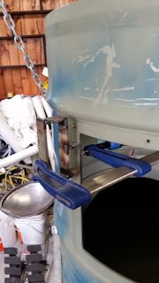
Fig. #1.  In order to drill the holes in the window frames straight, I made up this little jig that gets clamped to the frame and then drilled with the hand-drill, before being tapped with a thread.


Fig. #1.
05/12/2016

Fig. #2.  The jig clamped onto the front window frame.  The holes aren't perfectly straight but much better than freehand (which I tried but then had to weld over).

Fig. #2.
06/12/2016

Fig. #3 & 4.  Both the front and rear window frames with all their bolts.  All that's left to do is drill the same holes into the 3mm thick perspex.  I'll probably do this last thing before the pressure test so I can seal the windows on at the same time.

Fig. #3.
07/12/2016

Fig. #4.
09/12/2016

Next I hope to be designing in 3D the clamping mechanism to scale in Blender.  I've ordered a few parts for it online, which should be here in a few weeks.  Once this and the windows are on.  It's ready for a pressure test!

Hatch #3

Fig. #1 & 2.  On Monday I started putting together the hinge for the hatch, below shows the two pivoting shafts that will make it.  The reason for the two pivots is so that the dome can be clamped down easier.


Fig. #1.
05/12/2016

Fig. #2.
05/12/2016

Fig. #3 & 4.  Beginning to weld.  The hard part is not letting it get too hot and twist out of shape.

Fig. #3.
06/12/2016

Fig. #4.
06/12/2016

Fig. #5.  Ready for the dome.

Fig. #5.
06/12/2016

Fig. #6.  I bolted the dome in the center so I could tack weld the hinge into the correct place.

Fig. #6.
06/12/2016

Fig. #7.  A quick test to make sure it's moving correctly.  Next job is the rubber stops that it will limit it's movement backwards.

Fig. #7.
06/12/2016

Fig. #8, 9 & 10.  Here I'm about to weld the rubber feet onto the hinge to stop the hatch dome from going to far back.  The rubber will also stop the hull from being scratched.

Fig. #8.
06/12/2016

Fig. #9.
06/12/2016

Fig. #10.
06/12/2016

Fig. #11, 12, 13, 14 & 15.  Here I've just welded on the stops for the top part of the hinge.  The dome will rest on these ones.  The other pics just show off the dome resting on the hinge.

Fig. #11.
07/12/2016

Fig. #12.
07/12/2016

Fig. #13.
07/12/2016

Fig. #14.
07/12/2016

Fig. #15.
07/12/2016

Next will be a quick update on the window frames.

Saturday, 3 December 2016

Hatch #2

I received the dome on Monday and this afternoon I spent welding it together.  It cost about $300 to get made in Melbourne and shipped over.  It's made from 3mm thick stainless steel.

Fig. #1.  Shows the rim that was laser cut a few weeks ago.  Here I'm getting it lined up ready to tack in place.

Fig. #1.
03/12/2016

Fig. #2.  I drilled a hole through the desk and bolted the dome down onto some wood blocks to keep the whole lot steady while I worked on it.  I was also able to spin it around.

Fig. #2.
03/12/2016

Fig. #3.  After making my own steel roller (Fig. #9) I cut and tacked the middle in place.  This is to strengthen up the base so it doesn't bend when I clamp the hatch down during operation.

Fig. #3.
03/12/2016

Fig. #4.  Here I'm welding the back of the dome together.  The hinge will be welded to this.

Fig. #4.
03/12/2016

Fig. #5.  All welded and cleaned up.  To avoid the dome twisting as I welded it, I had to weld small parts at a time and then stagger them, one on one side, then one on the other.

Fig. #5.
03/12/2016

Fig. #6.  The outside all cleaned up and with smooth edges.

Fig. #6.
03/12/2016

Fig. #7.  Front view on the sub.

Fig. #7.
03/12/2016

Fig. #8.  Back view on the sub.

Fig. #8.
03/12/2016

Fig. #9.  On Thursday I built the roller, it took all day to build.  It can roll up to 3mm thick.  Here I've rolled the ring for the middle of the dome.

Fig. #9.
01/12/2016

Next I'll be working on the hinge for the hatch.