Thursday 31 December 2015

Hoisting Points #2

This is the last of the Hoisting Points updates.

I spent the last few hours putting the last two hoisting points together, then grinding all the welds flat and rounding edges on everything before giving it a coat of paint.  Tomorrow I'll be finishing of the rear dome and putting the motor and elevator system back on.

This weekend I'll make a start on, and hopefully finish, the mounts for the batteries.  After that I've got to make, and mount the throttle; mount the elevator and diving plane controls, and finish of the ballast release mechanism.  Once these are done I can paint the interior (only the front and back for now) then I can start work on the conning tower; hatch, windows and electronics, etc.

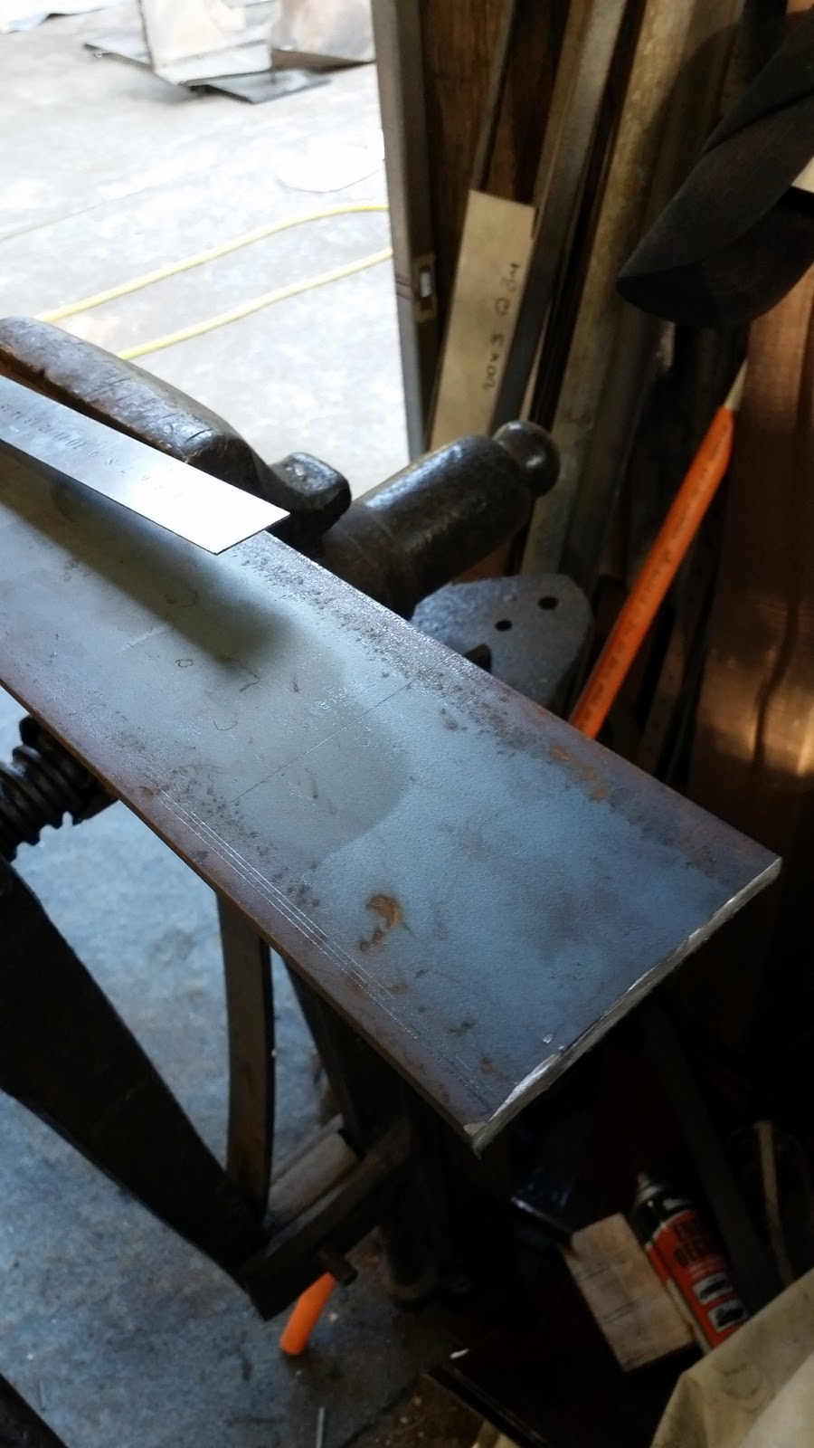
Fig. 1.  The left point ready to weld.

Fig. 1.
31/12/2015

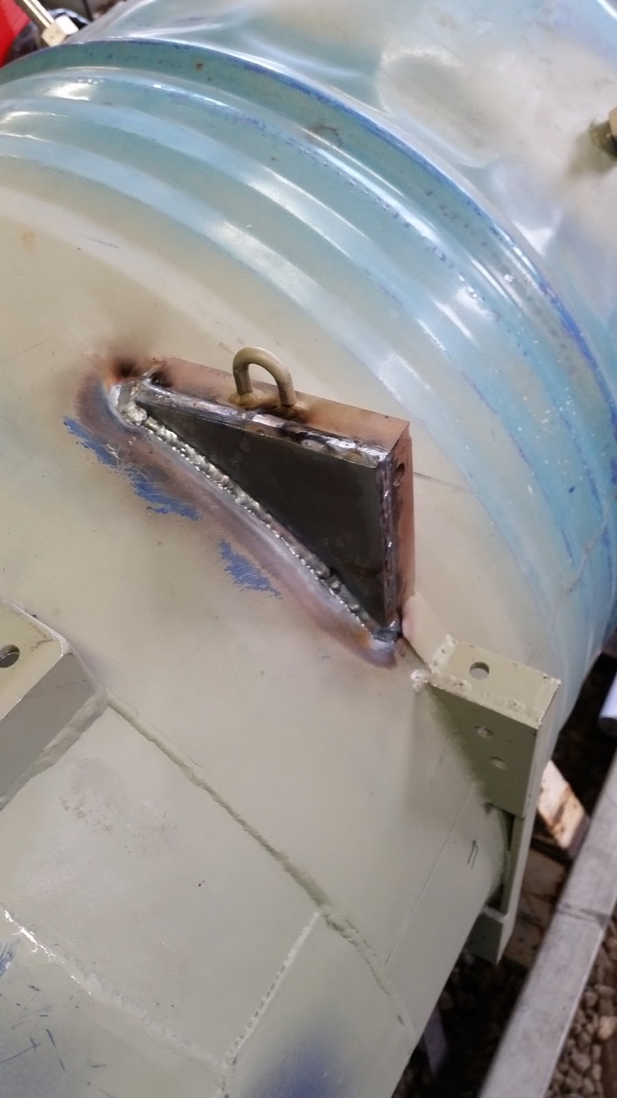
Fig. 2.  The left side welded.

Fig. 2.
31/12/2015

Fig. 3.  The right side welded.

Fig. 3.
31/12/2015

Fig. 4.  All done!

Fig. 4.
31/12/2015

Wednesday 30 December 2015

Hoisting Points #1

This evening I finished off two of the four remaining hoisting points.  The two I finished are the ones at the front.  Tomorrow night I'll finish off the the last two at the rear.

Fig. 1.  Marking out the pieces to cut.

Fig. 1.
30/12/2015

Fig. 2.  The two pieces are cut to shape.

Fig. 2.
30/12/2015

Fig. 3.  The two hoisting points that need reinforcement.  Each point will need to hold at least 200 kg and the current weld at the edge is two weak for that.

Fig. 3.
30/12/2015

Fig. 4.  I used a wire brush in the drill to scrap away the paint so it could be welded.

Fig. 4.
30/12/2015

Fig. 5.  Both parts have been ground at the curve so they can fit over the existing weld and they are now ready to weld in place.

Fig. 5.
30/12/2015

Fig. 6.  I  cleaned up the welds along the whole ballast tank brackets to make them look a little nicer.

Fig. 6.
30/12/2015

Fig. 7.  The other side all cleaned up to.

Fig. 7.
30/12/2015

Fig. 8.  The left side clamped in place.

Fig. 8.
30/12/2015

Fig. 9.  Welding and ready for a clean.

Fig. 9.
30/12/2015

Fig. 10.  Both sides welded and cleaned up ready for an undercoat of paint.

Fig. 10.
30/12/2015

Fig. 11.  Done.

Fig. 11.
30/12/2015

Tuesday 29 December 2015

Rear Dome #2

This afternoon I finished off another two panels.  There are two more to go and that will be my job for Friday.

Fig. 1.  The first segment all cleaned up and ready to weld.

Fig. 1.
29/12/2015

Fig. 2.  The top half is complete and the lower half is about to be tacked in place.  It was really hard to weld around the tight corners of the Elevator & Diving plane rig's brackets.  In hind sight it probably would have been a good idea to weld the panels on before the brackets.  Oh well, there's always next time.

Fig. 2.
29/12/2015

Fig. 3.  Segment one complete.

Fig. 3.
29/12/2015

Fig. 4.  Segment two in production.

Fig. 4.
29/12/2015

Fig. 5.  My fancy clamping rig.  It's awkward to setup, but it does the job in holding the edges down enough so I can tack weld them.

Fig. 5.
29/12/2015

Fig. 6.  Segment two tacked and ready to have the final weld.

Fig. 6.
29/12/2015

Fig. 7.  After about three hours a piece, both segments are welding and painted.

Fig. 7.
29/12/2015

Monday 28 December 2015

Rear Dome #1

This afternoon I continued welding the rear dome together.  For ages I couldn't figure out why my TIG's tungsten was wearing down from a point to a ball so quickly (a point allows more control over where the arc goes), then I realized I was using the wrong type of tungsten for DC welding.  Whoops.  But now with the right one I can weld nicer welds.

Fig. 1.  Here I'm cutting to shape one of the panels.  It becomes hard when there's no gaps anywhere to put clamps to hold it in place, and I can't use magnets everywhere because the magnetic fields disrupts the arc causing it to blow holes.  But time, patience and multitasking saw it through.

Fig. 1.
28/12/2015

Fig. 2.  After a lot of hammering and tack welding it's ready to seal up with the final weld.

Fig. 2.
28/12/2015

Fig. 3 & Fig. 4.  That parts done, now for the tiny hole.

Fig. 3.
28/12/2015

Fig. 4.
28/12/2015

Fig. 5.  The right side is done and has a coat of paint to stop rust.

Fig. 5.
28/12/2015

Fig. 6.  Tomorrow I plan to start on the left side.  If I can, hopefully by the end of the week (aka. next year) I'll have the whole rear dome complete and the inside will be ready for a touch up with paint.

Fig. 6.
28/12/2015

Saturday 26 December 2015

Elevator & Diving Controls #7

Fig. 1.  Today I started work on tidying up the conning tower's base.  Those ribs have been in the way since day one, my back has many scratches on it from crawling out of the front of the sub after welding.  I clamped the rib to the edge of the drum and did two small welds on either side of it then cut the rest of with the angle grinder.

Fig. 1.
26/12/2015

Fig. 2.  The front half complete.

Fig. 2.
26/12/2015

Fig. 3.  Both ends done.  There's a lot more room to move in there now, plus now that the ribs are welded in place I can start building the brackets that will hold the controls in place.

Fig. 3.
26/12/2015

Fig. 4.  The two 49 cm long 20 mm x 5 mm flat bars that will bolt onto the interior of the sub.  The controls will bolt onto these two bars.

Fig. 4.
26/12/2015

Fig. 5.  The control rods are all smoothed now.  I'll paint them once the perspex is cut to shape and the whole unit can be bolted to the sub.

Fig. 5.
26/12/2015
Fig. 6.  Here is the laser cutter template I'll use.  It'll be cut from 6 mm clear perspex.  The black is what the laser cutter will keep, the white is what will be cut out.  It took about an hour to design this one; I had to use Blender to make some of the control hub in 3D so that I could measure the centers of all the mounting holes and get 2D coordinates for the Laser Software.  I tested it on a few perspex off-cuts and I had to make a few tweaks for everything to line up nicely, and once I get some more perspex I'll cut two of them out and put them together.
Fig. 6.
26/12/2015

Tuesday 22 December 2015

Elevator & Diving Controls #6

Fig. 1 & Fig. 2.  I've made a slight design change to the controls.  I changed out the cables for a simple, flexible steel rectangle.  The reason being that, with the cables, when the lever was rotated it would change the shape of one end of the cable loop putting more tension on the cables, making it harder to achieve it's full range.  So reluctantly I replaced it.

Fig. 1
21/12/2015
Fig. 2
21/12/2015

Fig. 3.  Here is the first loop.  It's much stronger than the last one (though I really liked the last one, it was cool...) and it offers a larger rotating range.  It also leaves more room for the next loop for the other handle.

Fig. 3
21/12/2015

Fig. 4.  Here's both loops completed.  They do need some edge tidying though.  Once it's done I'll take it all apart, smooth and curve the edges then paint them so they're ready for the final assembly.

Fig. 4
22/12/2015

Fig. 5.  The second slider in place.

Fig. 5
22/12/2015

Fig. 6.  Here I'm trying to figure out how I'm going to weld the second handle on so that it lines up with the first and will also clear it as it rotates.  It ended up being a fraction too close, so rather than re-welding it, I took and extra 5 mm off each of the aluminium handles to make them 50 mm long.  Now there's plenty of room.

Fig. 6
22/12/2015

Fig. 7 & Fig. 8.  All done and ready to do the finishing touches like edge smoothing; painting and laser cutting the final perspex board to hold it to the sub.  After that, it'll be time to mount it in the sub and get ready for rigging up the elevators.

Fig. 7
22/12/2015


Fig. 8
22/12/2015

A video of this system in operation.


Tonight I'll be smoothing the edges of all the steel, and depending on the weather, I might paint them as well.

Sunday 20 December 2015

Elevator & Diving Controls #5

Yesterday I started welding the handle to the hub.  First I had to add a little bit to the top of the hub then cut it to about 10 mm long (Fig. 3) so that I could add a piece of steel and have it angle away from the curve of the hull.

Fig. 1
19/12/2015

Fig. 2
19/12/2015

Fig. 3
19/12/2015

Now I'm adding a piece around 8 cm long to the top of the hub at an angle of about 20 degrees.  This way I can have the controls sitting as close to the edge of the drum as possible and not have the handles hitting the top of the hull.

Fig. 4
19/12/2015

Today after work I added the threaded rod to the top of the lever.  This is where the handle will be bolted to.

Fig. 5
20/12/2015

I was originally going to make the handle from pine dowel, about 25 mm in diameter, but after drilling a 6 mm hole straight through it's center to slide onto the threaded rod, I saw that no matter how I drilled it, it would always follow the grain and be off center.  So a little annoyed at that, I decided to make it from aluminium.  Below I'm turning it down to 30 mm in diameter.

Fig. 6
20/12/2015

Once the center hole was drilled I began sanding it to make it shiny and smooth.

Fig. 7
20/12/2015

Nice.

Fig. 8
20/12/2015

In one end I drilled a 19 mm hole about 9 mm deep.  This will have a washer and a lock nut inside to keep it on the lever.

Fig. 9
20/12/2015

All bolted down.  I'm glad I made it from aluminium now.  It's stronger and much nicer.

Fig. 10
20/12/2015

Here's a quick little video showing the controls in operation.